AIR INLET DUCT |
An engine’s air inlet duct is normally considered an airframe part and made by aircraft manufacturer . During flight operation , it is very important to the engine performance . Engine thrust can be high only if the inlet duct supplies the engine with the required airflow at the highest posible pressure . The inlet duct has two engine functions and one aircraft function .
First : it must be able recover as much of the total pressure of the free air stream as posible and deliver this pressure to the front of the engine compressor .
Second : the duct must deliver air to the compressor under all flight conditions with a little turbulance .
Third : the aircraft is concerned , the duct must hold to a minimum of the drag.
The duct also usually has a diffusion section just ahead of the compressor to change the ram air velocity into higher static pressure at the face of the engine . This is called ram recovery . The inlet duct is built generally in the divergent shape (subsonic diffuser).
 |
Supersonic Duct |
The supersonic duct proplems start when the aircraft begins to fly at or near the speed of sound. At this speeds sonic shock waves are developed which , if not controlled , will give high duct loss in pressure and airflow , and will set up vibrating conditions in the inlet duct called inlet ” buzz ” . Buzz is an airflow instability caused by the shock wave rapidly being alternately swallowed and expelled at the inlet of the duct. Air enters the compressor section of engine must be slow to subsonic velocity. At supersonic speeds the inlet does the job by slowing the air with minimize energy loss and the temperature rise.
At transonic speeds the inlet duct is designed to keep shock waves out of the duct. This is done by locating the inlet duct behind a spike or probe which create the shock wave infront of inlet duct. This normal shock wave will produce a pressure rise and velocity decrease to subsonic speeds .

At higher mach numbers, the single normal shock wave is very strong and causes a great reduction in the total pressure recoverd by the duct and excessive air temperature rise inside the duct. The oblique shock wave will be used to slow the supersonic velocity down but still supersonic , the normal shock wave will drop the velocity to subsonic before the air enter to the compressor. Each reduce in velocity will increase a pressure. At very high mach number , the inlet duct must set up one or moreoblique shocks and a normal shock. |
COMPRESSOR |
The combustion of fuel and air at normal atmospheric pressure will not produce sufficient energy enough to produce useful work . The energy released by combustion is proportional to the mass of air consumed and its pressure. Therefore , higher pressure are needed to increase the efficiency of the combustion cycle . On the jet engines must rely upon some other means of compression .

Although centrifugal compressors are used in many jet engine , the efficiency level of a single stage is relatively low . The multistage of centrifugal compressor is better , but still do not compare with those axial flow compressors . Some small modern turboshaft and turboprop engines achieve good results by using a combination of axial flow and centrifugal compressor. |
Centrifugal compressor
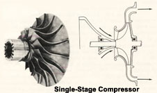
Centrifugal compressors operate by taking in outside air near their hub and rotating it by means of an impeller . The impeller , which is usually an aluminum alloy , guides the air toward the outer circumference of the compressor , building up the velocity of the air by means of high rotational speed of the impeller . The compressor consists of three main parts:
1) Impeller
2) A Diffuser
3) A Comprssor Manifold
Air leaves the Impeller at high speed , and flows through the diffuser which converts high velocity , kinetic energy to low velocity , high pressure energy . The diffuser also serves to direct airflow to the compressor manifold which acts as collector ring. They also delivery air to the manifold at a velocity and pressure which will be satisfactory for use in the burner section of the engine.
 |
Axial compressor
The air in an axial compressor flows in an axial direction through a series of rotating rotor blades and stationary stator vanes. The flow path of an axial compressor decreases in cross-section area in the direction of flow , reducing the volume of the air as compression progresses from stage to stage of compressor blades .
 
The air being delivered to the face of compressor by the air inlet duct, the incoming air passes through the inlet guide vanes . Air upon entering the first set of ratating blades and flowing in axial direction, is deflected in the direction of rotation . The air is arrested and turn as it is passed on to a set of stator vanes , following which it is again picked up by another set of rotating blades , and so on , through the compressor . The pressure of the air increases each time that it passes through a set of rotors and stators .
The aerodynamic principles are applied to the compressor blade design in order to increase efficiency . The blades are treated as lifting surfaces like aircraft wings or propeller blades . The cascade effect is a primary consideration in determining the airfoil section , angle of attack , and the spacing between blades to be used for compressor blade disign . The blade must be designed to withstand the high centrifugal forces as well as the aerodynamic loads to which they are subjected . The clearance between the rotating blades and their outer case is also very important . The rotor assembly turns at extreamely high speed , and must be rigid , well aligned and well balance . |
Compressor Surge and Compressor Stall
This characteristic has been called both ” Surge ” and ” Stall ” in the past , but is more properly called SURGE when it is response of the entire engine. The word stall applies to the action occuring at each individual compressor blade. Compressor surge , also called Compressor stall , is a phenomenon which is difficult to understand because it is usually caused by complex combination of factors . The basic cause of compressor surge is fairly simple , each blade in an axial flow compressor is a miniature airplane wing which , when subjected to a higher angle of attack , will stall just as an airplane stalls. Surge may define as results from an unstable air condition within the compressor. Pilot or engine operator has no instrument to tell him that one or more blades are stalling. He must wait until the engine surges to know that. The unstable condition of air is often caused from air piling up in the rear stages of the compressor. Surge may become sufficiently pronounce to cause lound bangs and engine vibration. In most case , this condition is of short duration , and will either correct itself or can be corrected by retarding the throttle or power lever to Idle and advanncing it again , slowly. Among other things , to minimize the tendency of a compressor to surge , the compressor can be “unload” during certain operating conditions by reducing the pressure ratio across the compressor for any giving airflow. One method of doing this is by bleeding air from the middle or toward the rear of the compressor. In dual axial compressor engines , air is often bled from between the low and the high pressure compressor. Air bleed ports are located in the compressor section. These ports are fitted with automatic , overboard bleed valves which usually operate in a specified range of engine RPM. Some large engine have been provided with variable-angle stators ( variable stators) in a few of the forward compressor stages. The angle of these vanes change automatically to prevent the choking of the downstream compressor stages as engine operating conditions vary. |
Turbofan Fan Section
They are considered as part of the compressor section in dual axial flow compressor engines because the fan is formed by the outer part of the front stages of the low compressor. The fan also seperate from the forward compressor and is driven by a freely rotating turbine of it own. The forward fan design is now used by most of engine manufacturers. In dual compressor engines , the fan is often integral with the relatively slow turning low compressor , which allows the fan blades to rotate at low tip speed.
 |


 On dual compressor engines , bleed air for service functions is also taken from additional ports located between the low and high compressors , or at intermediate stages in the high pressure compressor case . Air is bled from most engine vented over board out of the primary air flow path during certain engine operating conditions to prevent
  Primary and secondary fuel manifolds are often used on large engines . The primary manifold provides sufficient fuel for low thrust operation. At high thrust , the secondary , or main manifold cuts in , and fuel commences to flow through both primary and secondary elements of double-orifice nozzle. Usually , primary fuel is sprayed through a single orifice at the center of nozzle. Secondary fuel is sprayed through a number of orifices in a ring around the center orifice.


As compressed air specialists, Cooper Freer provides high quality air compressor, tools and accessories in Nottingham, Derby, UK, Milton Keynes, Kettering, Coventry, and Lincoln. We completely understand the needs of our customers and provide them reliable and energy efficient equipment.
ReplyDelete