General Information | |||||||||||||||||||||||||||||||||||||||||||||||||||||||||||
Thrust is the force that move the aircraft through the air.Thrust is generated by the propulsion system of the aircraft. There are different types of propulsion systems develop thrust in different ways, although it usually generated through some application of Newton’s Third Law. Propeller is one of the propulsion system. The purpose of the propeller is to move the aircraft through the air. The propeller consist of two or more blades connected together by a hub. The hub serves to attach the blades to the engine shaft. . | |||||||||||||||||||||||||||||||||||||||||||||||||||||||||||
 | |||||||||||||||||||||||||||||||||||||||||||||||||||||||||||
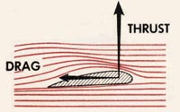
The blades are made in the shape of an airfoil like wing of an aircraft. When the engine rotates the propeller blades, the blades produce lift. This lift is called thrust and moves the aircraft forward. most aircraft have propellers that pull the aircraft through the air. These are called tractor propellers. Some aircraft have propellers that push the aircraft. These are called pusher propellers. | |||||||||||||||||||||||||||||||||||||||||||||||||||||||||||
 | |||||||||||||||||||||||||||||||||||||||||||||||||||||||||||
Description | |||||||||||||||||||||||||||||||||||||||||||||||||||||||||||
Leading Edge of the airfoil is the cutting edge that slices into the air. As the leading edge cuts the air, air flows over the blade face and the cambe side. | |||||||||||||||||||||||||||||||||||||||||||||||||||||||||||
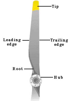 | |||||||||||||||||||||||||||||||||||||||||||||||||||||||||||
Blade Face is the surface of the propeller blade that corresponds to the lower surface of an airfoil or flat side, we called Blade Face. | |||||||||||||||||||||||||||||||||||||||||||||||||||||||||||
 | |||||||||||||||||||||||||||||||||||||||||||||||||||||||||||
Blade Back / Thrust Face is the curved surface of the airfoil. | |||||||||||||||||||||||||||||||||||||||||||||||||||||||||||
 | |||||||||||||||||||||||||||||||||||||||||||||||||||||||||||
Blade Shank (Root) is the section of the blade nearest the hub. | |||||||||||||||||||||||||||||||||||||||||||||||||||||||||||
Blade Tip is the outer end of the blade fartest from the hub. | |||||||||||||||||||||||||||||||||||||||||||||||||||||||||||
Plane of Rotation is an imaginary plane perpendicular to the shaft. It is the plane that contains the circle in which the blades rotate. | |||||||||||||||||||||||||||||||||||||||||||||||||||||||||||
 | |||||||||||||||||||||||||||||||||||||||||||||||||||||||||||
Blade Angle is formed between the face of an element and the plane of rotation. The blade angle throughout the length of the blade is not the same. The reason for placing the blade element sections at different angles is because the various sections of the blade travel at different speed. Each element must be designed as part of the blade to operate at its own best angle of attack to create thrust when revolving at its best design speed | |||||||||||||||||||||||||||||||||||||||||||||||||||||||||||
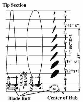 | |||||||||||||||||||||||||||||||||||||||||||||||||||||||||||
Blade Element are the airfoil sections joined side by side to form the blade airfoil. These elements are placed at different angles in rotation of the plane of rotation. | |||||||||||||||||||||||||||||||||||||||||||||||||||||||||||
The reason for placing the blade element sections at different angles is because the various sections of the blade travel at different speeds. The inner part of the blade section travels slower than the outer part near the tip of the blade. If all the elements along a blade is at the same blade angle, the relative wind will not strike the elements at the same angle of attack. This is because of the different in velocity of the blade element due to distance from the center of rotation. | |||||||||||||||||||||||||||||||||||||||||||||||||||||||||||
 | |||||||||||||||||||||||||||||||||||||||||||||||||||||||||||
Relative Wind is the air that strikes and pass over the airfoil as the airfoil is driven through the air. | |||||||||||||||||||||||||||||||||||||||||||||||||||||||||||
Angle of Attack is the angle between the chord of the element and the relative wind. The best efficiency of the propeller is obtained at an angle of attack around 2 to 4 degrees. | |||||||||||||||||||||||||||||||||||||||||||||||||||||||||||
Blade Path is the path of the direction of the blade element moves. | |||||||||||||||||||||||||||||||||||||||||||||||||||||||||||
 | |||||||||||||||||||||||||||||||||||||||||||||||||||||||||||
Pitch refers to the distance a spiral threaded object moves forward in one revolution. As a wood screw moves forward when turned in wood, same with the propeller move forward when turn in the air. | |||||||||||||||||||||||||||||||||||||||||||||||||||||||||||
Geometric Pitch is the theoritical distance a propeller would advance in one revolution. | |||||||||||||||||||||||||||||||||||||||||||||||||||||||||||
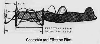 | |||||||||||||||||||||||||||||||||||||||||||||||||||||||||||
Effective Pitch is the actual distance a propeller advances in one revolution in the air. The effective pitch is always shorter than geometric pitch due to the air is a fluid and always slip. | |||||||||||||||||||||||||||||||||||||||||||||||||||||||||||
Forces and stresses acting on a propeller in flight | |||||||||||||||||||||||||||||||||||||||||||||||||||||||||||
The forces acting on a propeller in flight are : | |||||||||||||||||||||||||||||||||||||||||||||||||||||||||||
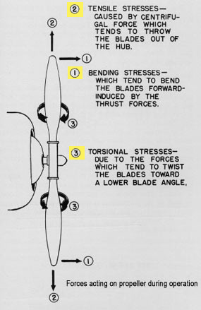 | |||||||||||||||||||||||||||||||||||||||||||||||||||||||||||
The stress acting on a propeller in flight are : | |||||||||||||||||||||||||||||||||||||||||||||||||||||||||||
| TYPE OF AIRCRAFT PROPELLERS | |||||||||||||||||||||||||||||||||||||||||||||||||||||||||||
Type of propellers | |||||||||||||||||||||||||||||||||||||||||||||||||||||||||||
In designing propellers, the maximum performance of the airplane for all condition of operation from takeoff, climb, cruising, and high speed. The propellers may be classified under eight general types as follows: | |||||||||||||||||||||||||||||||||||||||||||||||||||||||||||
1. Fixed pitch: The propeller is made in one piece. Only one pitch setting is possible and is usually two blades propeller and is often made of wood or metal. | |||||||||||||||||||||||||||||||||||||||||||||||||||||||||||
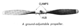
2. Ground adjustable pitch: The pitch setting can be adjusted only with tools on the ground before the engine is running. This type of propellers usually has a split hub. The blade angle is specified by the aircraft specifications. The adjustable – pitch feature permits compensation for the location of the flying field at various altitudes and also for variations in the characteristics of airplanes using the same engine. Setting the blade angles by loosened the clamps and the blade is rotated to the desired angle and then tighten the clamps. | |||||||||||||||||||||||||||||||||||||||||||||||||||||||||||
 | |||||||||||||||||||||||||||||||||||||||||||||||||||||||||||
3. Two-position : A propeller which can have its pitch changed from one position to one other angle by the pilot while in flight. | |||||||||||||||||||||||||||||||||||||||||||||||||||||||||||
4. Controllable pitch: The pilot can change the pitch of the propeller in flight or while operating the engine by mean of a pitch changing mechanism that may be operated by hydraulically. | |||||||||||||||||||||||||||||||||||||||||||||||||||||||||||
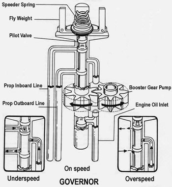
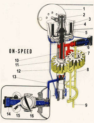
5. Constant speed : The constant speed propeller utilizes a hydraulically or electrically operated pitch changing mechanism which is controlled by governor. The setting of the governor is adjusted by the pilot with the rpm lever in the cockpit. During operation, the constant speed propeller will automatically changs its blade angle to maintain a constant engine speed. If engine power is increase, the blade angle is increased to make the propeller absorb the additional power while the rpm remain constant. At the other position, if the engine power is decreased, the blade angle will decrease to make the blades take less bite of air to keep engine rpm remain constant. The pilot select the engine speed required for any particular type of operation. | |||||||||||||||||||||||||||||||||||||||||||||||||||||||||||
6. Full Feathering : A constant speed propeller which has the ability to turn edge to the wind and thereby eliminate drag and windmilling in the event of engine failure. The term Feathering refers to the operation of rotating the blades of the propeller to the wind position for the purpose of stopping the rotation of the propeller to reduce drag. Therefore , a Feathered blade is in an approximate in-line-of-flight position , streamlined with the line of flight (turned the blades to a very high pitch). Feathering is necessary when the engine fails or when it is desirable to shutoff an engine in flight. | |||||||||||||||||||||||||||||||||||||||||||||||||||||||||||
 | |||||||||||||||||||||||||||||||||||||||||||||||||||||||||||
7. Reversing : A constant speed propeller which has the ability to assume a negative blade angle and produce a reversing thrust. When propellers are reversed, their blades are rotated below their positive angle , that is, through flat pitch, until a negative blade angle is obtained in order to produce a thrust acting in the opposite direction to the forward thrust . Reverse propeller thrust is used where a large aircraft is landed, in reducing the length of landing run. | |||||||||||||||||||||||||||||||||||||||||||||||||||||||||||
8. Beta Control : A propeller which allows the manual repositioning of the propeller blade angle beyond the normal low pitch stop. Used most often in taxiing, where thrust is manually controlled by adjusting blade angle with the power lever. | |||||||||||||||||||||||||||||||||||||||||||||||||||||||||||
| | |||||||||||||||||||||||||||||||||||||||||||||||||||||||||||
|
Your SEO optimized title
page contents
Wednesday, 26 October 2011
Aircraft Propellers
Subscribe to:
Post Comments (Atom)




No comments:
Post a Comment