| GENERAL |
This is just the basic informations for the beginners which did not know any things about the helicopter or airplane before and wants to know some principles that why the helicopter can fly but not in deep details. For the people that want to know more than what I have in here, please go to the text book which have many professors wrote them or go to the specific helicopter manuals. The details about the helicopter has so much to put it all in the WEB. |
| INTRODUCTION |
The wings of the airplane create a lift force when they move through the air. As we known,during flight, there are four forces acting on the helicopter or airplane and those are LIFT , DRAG , THRUST ,and WEIGHT .(please go back and see on What makes an airplane fly ? section).In order to make the wings to move through the air , of course, the plane itself has to move. A helicopter works by having its wings move through the air while the body stays still. The helicopter’s wings are called Main Rotor Blades. The shape and the angle of the blades move through the air will determine how much Lift force is created. After the helicopter lifted off the ground, the pilot can tilt the blades, causing the helicopter to tip forward or backward or sideward. |
| NOMENCLATURE AND TECHNICAL TERM |
Although we will describe certain terms or parts of helicopter more in the next sections as we go along, but we should familier with all of these terms in order to understand the helicopter better. |
Bernoulli’principle :This principle states that as the air velocity increases, the pressure decreases; and as the velocity decreases, the pressure increases . |
Airfoil : is technically defined as any surface, such as an airplane aileron, elevator, rudder, wing, main rotor blades, or tail rotor blades designed to obtain reaction from the air through which it moves. |
|
 |
|
Angle of Attack : is the acute angle measured between the chord of an airfoil and the relative wind. |
|
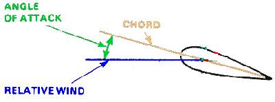 |
|
Angle of Incidence : is the acute angle between the wing’s chord line and the longitudinal axis of the airplane. (usually manufacturer had built the aircraft with the wing has some degrees to the horizontal plane or airplane longitudinal axis). |
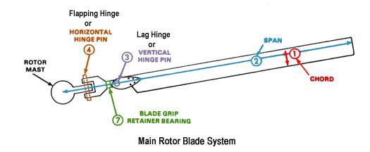
Blades : The blades of the helicopter are airfoils with a very high aspect ratio ( length to chord ). The angle of incidence is adjusted by means of the control from pilots.
The main rotor of the helicopter may have two, three,four , five or six blades, depending upon the design. The main rotor blades are hinged to the rotor head in such a manner that they have limited movement up and down and also they can change the pitch ( angle of incidence ). The controls for the main rotor are called Collective and Cyclic Controls. |
|
 |
|
The tail rotor is small blades may have two or four blades and mounted on the tail of the helicopter,it rotates in the vertical plane. The tail rotor is controlled by the rudder pedals. Its pitch can be changed as required to turn the helicopter in the direction desired. |
|
 |
|
Blade Root : The inner end of the blades where the rotors connect to the blade gripos. |
Blade Grips : Large attaching points where the rotor blade connects to the hub. |
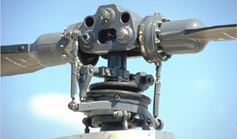
Rotor Hub : Sit on top of the mast , and connects the rotor blades to the control tubes. |
Main Rotor Mast : Rotating shaft from the transmission which connects the main rotor blades to helicopter fuselage. |
 |
|
Pitch Change Horn : to converts control tube movement to blade pitch. Control tube is a push-pull tubes that change the pitch of the rotor blades through the pitch changing horn. |
Swash Plate Assembly : The swash plate assembly consists of two primary elements through which the rotor mast passes. One element is a disc, linked to the cyclic pitch control. This disc is capable of tilting in any direction but does not rotate as the rotor rotates. This non-rotating disc, often refered to as the Stationary Star is attached by a bearing surface to a second disc, often refered to as the Rotating Star which turns with rotor and linked to the rotor blade pitch horns. |
|
 |
|
Transmission : The transmission system transmits engine power to the main rotor, tail rotor, generator and other accessories. The engine is operated at a relative high speed while the main rotor turns at a much lower speed. This speed reduction is accomplished through reduction gears in the Transmission System |
Lift : is produced by a lower pressure created on the upper surface of an airplane’s wings compared to the pressure on the wing’s lower surfaces,causing the wing to be LIFTED upward. The special shape of the airplane wing (airfoil) is designed so that air flowing over it will have to travel a greater distance and faster resulting in a lower pressure area (see illustration) thus lifting the wing upward. Lift is that force which opposes the force of gravity (or weight). |
|
  |
|
Lift depends upon (1) shape of the airfoil (2) the angle of attack (3) the area of the surface exposed to the airstream (4) the square of the air speed (5) the air density. |
 |
|
Relative Wind : is the direction of the airflow with respect to an airfoil or to the rotor blades. |
Pitch Angle : The rotor blade pitch angle is the acute angle between the blade chord line and the rotor plane of rotation.( you may understand as the angle of incidence ) . This pitch angle can be varied by the pilot through the use of cockpit controls ( collective and cyclic pitch control ). |
|
| History of Flight |
I will bring you only some of History that I think it is useful for you to know about how the helicopter was developed. They were so many great people contributed to this technologies but some of them were succeed and some were not. We all thanks to those people which make today happen. |
|
| Igor Sikorsky (United States) |
|
It was during 1909 that Igor Sikorsky Build his first machine in Russia in common many earier designed. But this first Sikorsky helicopter never left the ground, and a second which followed in 1910 ,he did not succeeded at this time so, he stopped and turn to fixed wing aircraft until 1930 . |
VS-300: In 1939, Sikorsky and a team of his engineers desinged the VS-300. The VS stood for VoughtSikorsky and the 300 indicated that it was Sikorsky’s third helicopter design.Vs300 had a75 hp Franklin 4cylinder engine. The basic structure was the heavygauge welded steel tubes. It had no covering at all and no instruments.It had three bladed main rotor and the anti-torque rotor at the rear. | 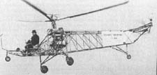
VoughtSikorsky VS-300 |
|
The R-4: In 1941, Sikorsky and Gluharaff designed the production model of VS300 and desinated VS316A . It was the bigger a bigger machine with an enclosed cabin and side by side seating and dual controls for two men crew 175 hp engine, a larger 36 ft (10.97 m.) rotor.The VS316A known by military designation XR-4 and YR4A. | 
VS-316A |
|
The R-5 and S-51: In 1943,Sikosky was working on all metal designated VS327 to meet requirement of USAAF known as XR5S and YR5A. It was better and bigger than R4.
In 1946, the first civilian type helicopter,S51 (four seats) was the first helicopter to be licenced by the US Civil Aviation Administration for commercial operation. | 
Sikorsky S-51 |
|
The S-55: In 1949, Sikorsky S-55 was located 600hp engine in the nose. For the first time, a helicopter was capable of lifting a heavy load up to ten soldiers,in addition to its two men crew. | 
Sikorsky S-55 |
|
| Focke Achgelis Fa61 (Germany) |
|
Fa-61: Germany stepped to the front in helicopter development with the Focke Achgelis Fa-61, which it has two three-bladed rotor mounted on outriggers and power by a 160 hp radial engine. The Fa-61 had controllable cyclic pitch and set many of records .
In 1938, Fa-61 made an altitude flight of 11,243 feet and cross-country of 143 miles.In this year, the german aviator Hanna Reitsch became the world’s first woman helicopter pilot by flying the Fa-61 in the Deustchland-halle in Berlin. Germany continued its helicopter development during world war two and was the first to place the helicopter,Flettner Kolibri, into mass production. | 
Focke Achgelis Fa-61 |
|
| Jaun de la Cierva (Spain) / Autogiro |
|
Cierva C30A : An Autogiro, in 1923 , Juan de la Cierva , a young engineer made the first successful flight of an autogiro. An autogiro operates on a different principle than a helicopter.That was the rotor of autogiro was not driven by the engine but rotated itself as the aircraft was drawn along by its propeller. Autogiro used extreamely short take-off and landing but it could not move sideways or hover in still air like a helicopter. The Autogiro’s rotor is designed so that a blade set at a low positive angle of pitch will rotate automatically as long as an airstream is kept flowing through the rotor .However, the technology of the rotor head and the rotor blade developed for autogiro contributed importantly to the development of the successful of helicopter. | 
Cierva C30A |
|
| Lawrence Bell (USA) |
|
Bell Model 30 :Bell Aircraft Corporation was formed in 1935 but it was until 1943 that the first Bell Helicopter Model 30 was successful flown. Several version of model 30 were built . Model 47 , built in 1945 and was granted the world’s first commercial helicopter licence. The Bell 47 developed into the most successful light – utility helicopters ever. A total of morethan 6,000 variants were built until the production was stopped in 1973. | 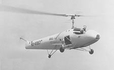
Bell Model 30 |
|
|
|
Principle of Helicopter Flight
( page 1 ) |
| GENERAL |
Helicopter, Lift is obtained by means of one or more power driven horizontal propellers which called Main Rotor. When the main rotor of helicopter turns it produces lift and reaction torque. Reaction torque tends to make helicopter spin. On most helicopters, a small rotor near the tail which called tail rotor compensates for this torque. On twin rotor helicopter the rotors rotate in opposite directions, their reactions cancel each other. |
|
 |
|
| Main Rotor |
The lifting force is produced by the main rotor . As they spin in the air and produced the lift. Each blade produces an equal share of the lifting force. The weight of a helicopter is divided evenly between the rotor blades on the main rotor system. If a helicopter weight 4000 lbs and it has two blades, then each blade must be able to support 2000 lbs.In addition to the static weight of helicopter ,each blade must be accept dynamic load as well . For example, if a helicopter pull up in a 1.5 g manouver (1.5 time the gravity force), then the effective weight of helicopter will be 1.5 time of static helicopter weight or 6000 lbs. due to gravitational pull. |
| Tail Rotor |
The tail rotor is very important. If you spin a rotor with an engine, the rotor will rotate,but the engine and helicopter body will tend to rotate in opposite direction to the rotor. This is called Torque reaction. Newton’s third law of motion states , ” to every action there is an equal and opposite reaction” . The tail rotor is used to compensates for this torque and hold the helicopter straight. On twin-rotors helicopter , the rotors spin in opposite directions, so their reactions cancel each other. |
|
 |
|
The tail rotor in normally linked to the main rotor via a system of driveshafts and gearboxes , that means if you turn the main rotor , the tail rotor is also turn.Most helicopter have a ratio of 3:1 to 6:1 . That is, if main rotor turn one rotation , the tail rotor will turn 3 revelutions (for 3:1)or 6 revolutions (for 6:1). In most helicopter the engine turns a shaft that connected to an input quill in the transmission gearbox. the main rotor mast out to the top and tail rotor drive shafts out to the tail from the tranmission gear box. |
|
 |
|
| Dissymmetry of Lift |
All rotor systems are subject to Dissymmetry of Lift in forward flight . At a hover , the lift is equal across the entire rotor disk . As the helicopter gain air speed , the advanceing blade develops greater lift because of the increased airspeed and the retreating blade will produce less lift , this will cause the helicopter to roll (for example: if rotor speed = 400 km/hr , helicopter move forward=100 km/hr then advancing blade will have speed=500 km/hr but the retreating blade will has moving speed of only 300 kr/hr ) . This has to be compensated for in some way . |
|
 |
|
| Blade Flapping |
Dissymmetry of lift is compensated for by Blade flapping. Because of the increased airspeed and lift on the advancing blade will cause the blade to flap up and decreasing the angle of attack . The decreased lift on the retreating blade will cause the blade to flap down and increasing the angle of attack . The combination of decreased angle of attack on the advancing blade and increased angle of attack on the retreating blade through blade flapping action tends to equalize the lift over the two halves of the rotor disc. |
|
 |
|

|
|
Flight Direction Control
( page 1 ) |
| GENERAL |
Helicopter, Lift is obtained by means of one or more power driven horizontal propellers which called Rotors. When the rotors of helicopter turns it produces lift and reaction torque, reaction torque which tends to make helicopter spin. on most helicopters a small rotor near the tail which called tail rotor compensates for this torque. On twin rotor helicopter the rotors rotate in opposite directions, their reactions cancel each other. The direction of helicopter is controlled by inclining the axis of the main rotor path in that direction. |
| Function of Controls |
There are three major controls in the helicopter that the pilot must use during flight. They are : ( 1 ) Collective pitch control. ( 2 ) Anti Torque Pedals or Tail Rotor Control. ( 3 ) Cyclic Stick Control. |
|
  |
|
Collective Control
The collective pitch lever or stick is located by the left side of the pilot’s seat and is operated with the left hand. The collective is used to increase main rotor pitch at all points of the rotor blade rotation. It increases or decreases total rotor thrust. The collective lever is connected to the swash plate by a series of bush pull tubes. Raising the collective lever increases the pitch on the main rotor blade, lowering the collective lever decreases the main rotor blade pitch. The amount of movement of th elever determines the amount of blade pitch change. As the angle of attack increase, drag increases and Rotor RPM and Engine RPM tend to decrease . As the angle of attack decreases, drag decreases and the RPM tend to increase.Since it is essential that the RPM remain constant, there must be some means of making a proportionate change in power to compensate for the change in drag. This coordination of power change with blade pitch angle change is controlled through a collective pitch lever- trottle control cam linkage which automatically increases power when the collective pitch lever is raised and decreases power when the lever is lowered. |
|
 |
|
The picture above is the typical collective lever but the detail of control may varies depend on each munufacturer .The main functions are still the same for all helicopters.
Collective Lever is connected to the rotor system via push pull tubes. It also has droop com pensation devics which sense change in the collective pitch lever and increases or decreases fuel to the engine automatically somewhat in anticipated of a change in power required. This helps to minimize the RPM fluctuations during collective pitch change.
Engine Control (Emergency) is the throttle twist grip. During emergency condition, between flight and flight idle positions. This is useful during any event which would cause engine or rotor RPM to go too high or while landing after a tail rotor failure.
Idle Release Button, when the throttle is rolled from ” off ” to ” idle ” the idle release button snaps into a detent which prevents the throttle from being rolled back to ” off “
Starter Button : Pushing this button will cause the starter / generator to act as a starter motor ( Starter / Generator is a component that funtion in either mode as a starter or generator ) , turning over the engine.
Landing Light Switch has a three position which are ” off ” , ” forward ” and “both ” . In forward , only the forward light is activated. In both, the forward and downward lights are activated .
Power Trim Switch ,by holding it in ” increase ” or ” decrease ” the pilot can set the RPM that the pilot attempt to maintain. |
|
|
| Function of Controls (Continue) |
|
Anti-Torque Pedals or Tail Rotor Control
In accordance with Newton’s law of action and reaction, the helicopter fuselage tends to rotate in the direction opposite to the rotor blades . This effect is called torque . Torque must be counteracted and controlled to make flight is possible . Compensation for torque in a single main rotor helicopter is accomplished by means of a variable pitch antitorque rotor (tail rotor) located on the end of the tail boom extension at the rear of fuselage. |
|
  |
|
Heading Control : In addition to counteracted torque, the tail rotor and its control linkage also permit control of the helicopter heading during flight . Application of more control than is necessary to counteract torque will cause the nose of helicopter to turn in the direction of pedal movement. |
|
 |
|
In forward flight , the pedals are not used to control the heading of the helicopter (except during portions of crosswind takeoff and approach). They are used to compensate for torque to put the helicopter in longitudinal trim so that coordinated flight can be maintained.
The thrust of the tail rotor is depend upon the pitch angle of the tail rotor blades. The tail rotor may have a positive pitch angle or it may have a negative pitch angle which to push the tail to the right or pull the tail to the left. |
|
 |
|
With the right pedal pressed or moved forward of the neutral position will cause the tail rotor blades to change the pitch angle and the nose of helicopter will yaw to the right . With the left pedal pressed or moved forward of the neutral position will cause the tail rotor blades to change the pitch angle opposite to the right pedal and the nose of helicopter will yaw to the left. |
|
|
| Function of Controls (Continue) |
|
Cyclic Control
As mention earier , the total lift force is always perpendicular to the tip-path plane of the main rotor. When the tip path plane is tilt away from the horizontal, the lift -thrust force is divide into two components of forces that are, the horizontal acting force, thrust and the upward acting force, lift. |
  |
|
The purpose of the cyclic pitch control is to tilt the tip path plane in the direction that horizontal movement is desired. The thrust component of force then pulls the helicopter in the direction of rotor tilt. The cyclic control changes the direction of this force,thus controlling the attitude and air speed of helicopter. |
 |
|
The rotor disc tilts in the same direction of the cyclic stick was moved. If the cyclic stick is moved forward, the rotor disc tilt forward: if the cyclic is moved aft, the rotor disc tilt aft, and so on. The rotor disc will always tilt in the same direction that the cyclic stick is moved. |
 |
|
The above picture is only typical for cyclic control stick which different manufacturer will have some detail different but the main fuction is the same.
The radio switch is used for pilot to transmit radio by clicking the switch.
The trim switch , pilot use this switch to neutralize stick force . Pilot can use the trim switch to put the stick to the right , left , forward or backward . This runs electric motor which will tension the spring which will tend to hold the stick. The cyclic will stay where it is even the pilot were let it go . This also release tension from pilot.
The cargo release switch is the option switch, some manufacturer may have other function switch. |
 |
|
|


No comments:
Post a Comment