General
 The landing gear on the NG has been extensively redesigned. The nose gear is 3.5″ longer to relieve higher dynamic loads and the nose-wheelwell has been extended 3″ forward. The main gear is also longer to cater for the increased fuselage lengths of the -8/900 series and is constructed from a one piece titanium gear beam based on 757/767 designs. There is an externally mounted trunnion bearing on the gear, a re-located gas charging valve, and the uplock link is separate from the reaction link. It is fitted with 43.5″ tyres and digital antiskid.
Unfortunately the 737-700 was particularly prone to a dramatic shudder from the main landing gear if you tried to land smoothly. Fortunately Boeing started fitting shimmy dampers to this series from L/N 406 (Nov 1999) and a retrofit was made available.
One of the peculiarities of the 737 is that it invariably appears to crab when taxying. Theories for this include: A slightly castoring main gear to increase the crosswind capability; Play in the scissor link pins; Weather-cocking into any crosswind impinging on the fin; Torque reaction from the anti-collision light !!! Engineers will tell you that is due to the main gear having a couple of degrees of play due to the shimmy dampers.

Tyres
Tyres are tubeless and inflated with nitrogen. Pressures vary with series, maximum taxi weight, temperature and size of tyres. Unfortunately this large variation in tyre pressures makes it difficult to know your aquaplaning speed. The table below should prove helpful, notice how the aquaplaning speeds are all just below the typical landing speeds. Note: Once aquaplaning has started, it will continue to a much lower speed.| Series | Main Gear | Aquaplaning Speed | Nose Gear | Aquaplaning Speed |
| Originals | 96 – 183psi | 84 – 116Kts | 125 – 145psi | 96 – 104Kts |
| Classics | 185 – 217psi | 118 – 128Kts | 163 – 194psi | 111 – 121Kts |
| NG’s | 117 – 205psi | 93 – 123Kts | 123 – 208psi | 95 – 124Kts |
The speed rating of all tyres is 225mph (195kts).

Gear Seals
 Notice that none of the 737 series have ever had full main gear doors. Instead the outer wall of the tyres meet with aerodynamic seals in the wheel well to make a smooth surface along the underside of the aircraft. The first few 737′s had inflatable seals which were inflated by bleed air when the gear was either up or down and deflated during transit. The landing gear panel had a NOT SEALED caption which would illuminate during transit (normal), if it illuminated at any other time you could have a puncture and the seal could be depressurised with the GEAR SEAL SHUTOFF switch to save bleed requirements.
These were soon dropped as being too complicated and a similar drag and noise advantage was achieved with the present fixed rubber seals.
Brakes
The standard 737 brakes are a steel alloy called Cerametalix(R) with versions made by either Goodrich or Honeywell. Since 2008 the 737NG has had a carbon brake option from either Goodrich with Duracarb(R) or Messier-Bugatti with SepCarb® III-OR. They are both about 300kgs lighter than steel and last twice as long.The brake pressure gauge merely shows the pressure of the air side of the accumulator and should normally indicate 3000psi. The normal brake system and autobrakes are powered by hydraulic system B. If brake pressure drops below 1500psi, hydraulic system A automatically provides alternate brakes which are manual only (ie no autobrake) and the brake pressure returns to 3000psi. Antiskid is available with alternate brakes, but not touchdown or locked wheel protection on series before the NG’s.
If both system A and B lose pressure, the accumulator isolation valve closes at 1900psi and you are just left with residual hydraulic pressure and the pre-charge. The gauge will indicate approx 3000psi and should provide 6 full applications of brake power through the normal brake lines (so full antiskid is available) As the brakes are applied the residual pressure reduces until it reaches 1000psi at which point you will have no more braking available.
If the brake pressure gauge ever shows zero, this merely indicates that the pre-charge has leaked out, normal and alternate braking are unaffected if you still have the hydraulic systems (see QRH). The accumulator also provides pressure for the parking brake.
Note that on the 737-1/200, hydraulic system A operates the inboard brakes and system B operates the outboard brakes. Both brake pressures are indicated on the single hydraulic brake pressure gauge.
There are four thermal fuse plugs in the inner wheel half which prevent tyre explosion caused by hot brakes. The plugs melt to release tyre pressure at approx 177C (351F).
| Brake Pressure Indication (psi) | Condition |
| 3000 | Normal. |
| 3000 | No hydraulics, minimum 6 applications of brakes available with accumulator. |
| 1000 | No hydraulics, accumulator used up. |
| Zero | No pre-charge, normal braking available with hydraulics. |
 Brake Accumulator |  Brake Wear Pin |
Autobrakes


| Autobrake Selector | Max Pressure at Brakes (PSI) | Deceleration Rate (ft/sec²) |
| 1 | 1250 | 4 |
| 2 | 1500 | 5 |
| 3 | 2000 | 7.2 |
| Max | 3000 | 12 (below 80kts) |
| “ | “ | 14 (above 80kts) |
| RTO | Full | Not Controlled |
Notice from the table above that autobrake Max does not give full brake pressure. For absolute maximum braking on landing, select autobrake Max to assure immediate application after touch down then override with full toe brake pressure.
Using high autobrake settings with idle reverse is particularly hard on the brakes as they will be working for the given deceleration rate without the assistance of full reverse thrust.
To cancel the autobrake on the landing roll with toe brakes you must apply a brake pressure in excess of 800psi (ie less than that required for autobrake 1). This is more difficult on the NG’s because the feedback springs on the brake pedals are stiffer. Autobrake can also be cancelled by putting the speedbrake lever down or by switching the autobrake off. I would advise against the latter in case you accidentally select RTO and get the full 3000psi of braking!
Occasionally you may see the brakes (rather than the cabin crew!) smoking during a turnaround. This may be due to hard braking at high landing weights. But the most common reason is that too much grease is put on the axle at wheel change so that when the wheel is pushed on, the grease is deposited inside the torque tube; when this gets hot, it smokes. It could also be contamination from hydraulic fluid either from bleeding operation or a leak either from the brakes or another source.
Photos
 | The landing gear panel is located between the engine instruments and F/O’s instrument panel.The Green lights tell you that the gear is down and locked and the red lights warn you if the landing gear is in disagreement with the gear lever position. With the gear UP and locked and the lever UP or OFF, all lights should be extinguished. On a couple of occasions I have seen 3 reds and 3 greens after the gear has been selected down. This was because the telescopic gear handle had not fully compressed back toward the panel. If this happens to you, give it a tap back in and the red lights will extinguish. |
 | 737′s used for cargo operations have an extra set of green “GEAR DOWN” lights on the aft overhead panel. This is because with the cabin filled with freight, the main gear downlock viewer could not be guaranteed to be accessible in-flight. The NG’s also have these lights because they do not have gear downlock viewers installed. |
 Main gear viewer (not NG’s) | If any green gear lights do not illuminate after the gear is lowered, you might consider a visual inspection through the gear viewers. The main gear viewer is in the cabin and the nose gear viewer is on the flight deck. The main gear viewers are not installed on NG series aircraft.This is the main gear viewer and it is located in the isle, just behind the emergency exit row. The first time you look through a viewer it will probably take you several minutes to find what you are looking for, hardly ideal if you are in the situation for real so it is worth acquainting yourself with its use. |
 Main gear viewer prisms (not NG’s) | There are two prisms, one for each main gear leg. Don’t forget to switch on the wheel-well light if at night. |
 Gear locked marks (not NG’s) | Eventually, you should be able to see three red marks on the undercarriage, if they line up then your gear is certainly down and probably locked. |
 Main wheel-well and downlock viewer (classics) | The location of the main gear downlock viewer in the wheel well can be clearly seen in this photograph. |
 Nosegear viewer (not NG’s) | The nosegear viewer is located under a panel toward the aft of the flightdeck. There is no prism, just a long tube. This viewer directs your eye exactly toward the correct place for viewing but is usually more dirty. The nosegear down marks are two red arrows pointing at each other. |
 Manual gear extension access hatch Manual gear extension access hatch | If the gear fails to extend properly or hydraulic system A is lost, the gear can be manually extended by pulling the manual gear extension handles, located in the flight deck. This should be done in accordance with the QRH procedure.On NG aircraft opening this hatch affects the operation of landing gear extension & retraction. |
 Tyre damage fitting – NG only Tyre damage fitting – NG only | This pin is designed to detect any loose tyre tread during gear retraction. If any object impacts on it during retraction, then the gear will automatically extend. The affected gear cannot be retracted until this fitting is replaced. There is one pin at the aft outside of each main wheel well. |
| Other landing gear system photographs | |
 Nosewheel door (classic) Nosewheel door (classic) |  Gravel Deflector (-200) |
 |  Tail skid (-400) Tail skid (-400) |
General
The landing gear on the NG has been extensively redesigned. The nose gear is 3.5″ longer to relieve higher dynamic loads and the nose-wheelwell has been extended 3″ forward. The main gear is also longer to cater for the increased fuselage lengths of the -8/900 series and is constructed from a one piece titanium gear beam based on 757/767 designs. There is an externally mounted trunnion bearing on the gear, a re-located gas charging valve, and the uplock link is separate from the reaction link. It is fitted with 43.5″ tyres and digital antiskid.Unfortunately the 737-700 was particularly prone to a dramatic shudder from the main landing gear if you tried to land smoothly. Fortunately Boeing started fitting shimmy dampers to this series from L/N 406 (Nov 1999) and a retrofit was made available.
One of the peculiarities of the 737 is that it invariably appears to crab when taxying. Theories for this include: A slightly castoring main gear to increase the crosswind capability; Play in the scissor link pins; Weather-cocking into any crosswind impinging on the fin; Torque reaction from the anti-collision light !!! Engineers will tell you that is due to the main gear having a couple of degrees of play due to the shimmy dampers.
Tyres
Tyres are tubeless and inflated with nitrogen. Pressures vary with series, maximum taxi weight, temperature and size of tyres. Unfortunately this large variation in tyre pressures makes it difficult to know your aquaplaning speed. The table below should prove helpful, notice how the aquaplaning speeds are all just below the typical landing speeds. Note: Once aquaplaning has started, it will continue to a much lower speed.| Series | Main Gear | Aquaplaning Speed | Nose Gear | Aquaplaning Speed |
| Originals | 96 – 183psi | 84 – 116Kts | 125 – 145psi | 96 – 104Kts |
| Classics | 185 – 217psi | 118 – 128Kts | 163 – 194psi | 111 – 121Kts |
| NG’s | 117 – 205psi | 93 – 123Kts | 123 – 208psi | 95 – 124Kts |
The speed rating of all tyres is 225mph (195kts).
Gear Seals
Notice that none of the 737 series have ever had full main gear doors. Instead the outer wall of the tyres meet with aerodynamic seals in the wheel well to make a smooth surface along the underside of the aircraft. The first few 737′s had inflatable seals which were inflated by bleed air when the gear was either up or down and deflated during transit. The landing gear panel had a NOT SEALED caption which would illuminate during transit (normal), if it illuminated at any other time you could have a puncture and the seal could be depressurised with the GEAR SEAL SHUTOFF switch to save bleed requirements.These were soon dropped as being too complicated and a similar drag and noise advantage was achieved with the present fixed rubber seals.
Brakes
The standard 737 brakes are a steel alloy called Cerametalix(R) with versions made by either Goodrich or Honeywell. Since 2008 the 737NG has had a carbon brake option from either Goodrich with Duracarb(R) or Messier-Bugatti with SepCarb® III-OR. They are both about 300kgs lighter than steel and last twice as long.The brake pressure gauge merely shows the pressure of the air side of the accumulator and should normally indicate 3000psi. The normal brake system and autobrakes are powered by hydraulic system B. If brake pressure drops below 1500psi, hydraulic system A automatically provides alternate brakes which are manual only (ie no autobrake) and the brake pressure returns to 3000psi. Antiskid is available with alternate brakes, but not touchdown or locked wheel protection on series before the NG’s.
If both system A and B lose pressure, the accumulator isolation valve closes at 1900psi and you are just left with residual hydraulic pressure and the pre-charge. The gauge will indicate approx 3000psi and should provide 6 full applications of brake power through the normal brake lines (so full antiskid is available) As the brakes are applied the residual pressure reduces until it reaches 1000psi at which point you will have no more braking available.
If the brake pressure gauge ever shows zero, this merely indicates that the pre-charge has leaked out, normal and alternate braking are unaffected if you still have the hydraulic systems (see QRH). The accumulator also provides pressure for the parking brake.
Note that on the 737-1/200, hydraulic system A operates the inboard brakes and system B operates the outboard brakes. Both brake pressures are indicated on the single hydraulic brake pressure gauge.
There are four thermal fuse plugs in the inner wheel half which prevent tyre explosion caused by hot brakes. The plugs melt to release tyre pressure at approx 177C (351F).
| Brake Pressure Indication (psi) | Condition |
| 3000 | Normal. |
| 3000 | No hydraulics, minimum 6 applications of brakes available with accumulator. |
| 1000 | No hydraulics, accumulator used up. |
| Zero | No pre-charge, normal braking available with hydraulics. |
| Brake Accumulator | Brake Wear Pin |
Autobrakes
| Autobrake Selector | Max Pressure at Brakes (PSI) | Deceleration Rate (ft/sec²) |
| 1 | 1250 | 4 |
| 2 | 1500 | 5 |
| 3 | 2000 | 7.2 |
| Max | 3000 | 12 (below 80kts) |
| “ | “ | 14 (above 80kts) |
| RTO | Full | Not Controlled |
Notice from the table above that autobrake Max does not give full brake pressure. For absolute maximum braking on landing, select autobrake Max to assure immediate application after touch down then override with full toe brake pressure.
Using high autobrake settings with idle reverse is particularly hard on the brakes as they will be working for the given deceleration rate without the assistance of full reverse thrust.
To cancel the autobrake on the landing roll with toe brakes you must apply a brake pressure in excess of 800psi (ie less than that required for autobrake 1). This is more difficult on the NG’s because the feedback springs on the brake pedals are stiffer. Autobrake can also be cancelled by putting the speedbrake lever down or by switching the autobrake off. I would advise against the latter in case you accidentally select RTO and get the full 3000psi of braking!
Occasionally you may see the brakes (rather than the cabin crew!) smoking during a turnaround. This may be due to hard braking at high landing weights. But the most common reason is that too much grease is put on the axle at wheel change so that when the wheel is pushed on, the grease is deposited inside the torque tube; when this gets hot, it smokes. It could also be contamination from hydraulic fluid either from bleeding operation or a leak either from the brakes or another source.
Photos
| | The landing gear panel is located between the engine instruments and F/O’s instrument panel.The Green lights tell you that the gear is down and locked and the red lights warn you if the landing gear is in disagreement with the gear lever position. With the gear UP and locked and the lever UP or OFF, all lights should be extinguished. On a couple of occasions I have seen 3 reds and 3 greens after the gear has been selected down. This was because the telescopic gear handle had not fully compressed back toward the panel. If this happens to you, give it a tap back in and the red lights will extinguish. |
| | 737′s used for cargo operations have an extra set of green “GEAR DOWN” lights on the aft overhead panel. This is because with the cabin filled with freight, the main gear downlock viewer could not be guaranteed to be accessible in-flight. The NG’s also have these lights because they do not have gear downlock viewers installed. |
| Main gear viewer (not NG’s) | If any green gear lights do not illuminate after the gear is lowered, you might consider a visual inspection through the gear viewers. The main gear viewer is in the cabin and the nose gear viewer is on the flight deck. The main gear viewers are not installed on NG series aircraft.This is the main gear viewer and it is located in the isle, just behind the emergency exit row. The first time you look through a viewer it will probably take you several minutes to find what you are looking for, hardly ideal if you are in the situation for real so it is worth acquainting yourself with its use. |
| Main gear viewer prisms (not NG’s) | There are two prisms, one for each main gear leg. Don’t forget to switch on the wheel-well light if at night. |
| Gear locked marks (not NG’s) | Eventually, you should be able to see three red marks on the undercarriage, if they line up then your gear is certainly down and probably locked. |
| Main wheel-well and downlock viewer (classics) | The location of the main gear downlock viewer in the wheel well can be clearly seen in this photograph. |
| Nosegear viewer (not NG’s) | The nosegear viewer is located under a panel toward the aft of the flightdeck. There is no prism, just a long tube. This viewer directs your eye exactly toward the correct place for viewing but is usually more dirty. The nosegear down marks are two red arrows pointing at each other. |
| Manual gear extension access hatch | If the gear fails to extend properly or hydraulic system A is lost, the gear can be manually extended by pulling the manual gear extension handles, located in the flight deck. This should be done in accordance with the QRH procedure.On NG aircraft opening this hatch affects the operation of landing gear extension & retraction. |
| Tyre damage fitting – NG only | This pin is designed to detect any loose tyre tread during gear retraction. If any object impacts on it during retraction, then the gear will automatically extend. The affected gear cannot be retracted until this fitting is replaced. There is one pin at the aft outside of each main wheel well. |
| Other landing gear system photographs | |
| Nosewheel door (classic) | Gravel Deflector (-200) |
| | Tail skid (-400) |
Hydraulics -B737
Pumps

The hydraulic pump panel -1/200
The 737-1/200 had system A powered by the two Engine Driven Pumps (EDP’s) and system B powered by the two Electric Motor Driven Pumps (EMDP’s). There is also a ground interconnect switch to allow system A to be powered when the engines are shut down.
The hydraulic pump panel -300 onwards
From the 737-300 onwards each hydraulic system had both an EDP and an EMDP for greater redundancy in the event of an engine or generator failure.To see the hydraulic systems (pumps, reservoirs, gauges etc) see wheel-well fwd
Services Supplied
| Services Supplied | ||
| System A | System B | Standby |
| A/P “A” | A/P “B” | |
| Ailerons | Ailerons | |
| Rudder | Rudder | Rudder |
| Yaw damper | Standby yaw damper (as installed) | |
| Elev & Elev feel | Elev & Elev feel | |
| Inboard flight spoiler | Outboard flight spoiler | |
| Ground spoilers | ||
| L/E flaps & slats | L/E flaps & slats (for extension only) | |
| T/E flaps | ||
| PTU for autoslats | Autoslats | |
| No1 thrust reverser | No2 thrust reverser | Nos 1 & 2 thrust reversers (slow) |
| Nose wheel steering | Alt nose wheel steering | |
| Alternate brakes (man only) | Normal (auto & man) brakes | |
| Landing gear | Landing gear transfer unit (retraction only) | |
Reservoirs
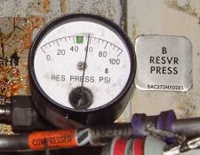
Hydraulic System B Reservoir Pressure Gauge
The hydraulic reservoirs are pressurised from the pneumatic manifold to ensure a positive flow of fluid reaches the pumps. A from the left manifold and B from the right (see wheel-well fwd). The latest 737′s (mid 2003 onwards) have had their hydraulic reservoir pressurisation system extensively modified to fix two in-service problems 1) hydraulic vapours in the flight deck caused by hydraulic fluid leaking up the reservoir pressurisation line back to the pneumatic manifold giving hydraulic fumes in the air-conditioning and 2) pump low pressure during a very long flight in a cold soaked aircraft. The latter is due to water trapped in the reservoir pressurisation system freezing blocking reservoir bleed air supply. Aircraft which have been modified (SB 737-29-1106) are recognised by only having one reservoir pressure gauge in the wheel well.Fuses
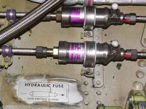
Hydraulic Fuses
Also in the wheel well can be seen the hydraulic fuses. These are essentially spring-loaded shuttle valves which close the hydraulic line if they detect a sudden increase in flow such as a burst downstream, thereby preserving hydraulic fluid for the rest of the services. Hydraulic fuses are fitted to the brake system, L/E flap/slat extend/retract lines, nose gear extend/retract lines and the thrust reverser pressure and return lines.

On pre-EIS aircraft (before 1988) the hydraulic gauges were similar to the 737-200. There are now separate quantity gauges since the reservoirs are not interconnected and the markings have been simplified. There is now just a single brake pressure gauge showing the normal brake pressure from system B.

737-200 Hydraulic Gauges.
Notice that there is only a system A quantity gauge, this is because on the 737-1/200 system B is filled from system A reservoir. System B quantity is monitored by the amber “B LOW QUANTITY” light above. The hydraulic brake pressure gauge has two needles because system A operates the inboard brakes and system B the outboard brakes, each has an accumulator.Quantities
This table shows the nominal quantities at different levels in the reservoirs| Aircraft Series | Originals | Classics | NG’s | |
| System | Gauges | EIS | Upper CDU | |
| A | Full level | 3.6 USG | 100% | 100% (5.7Gal / 21.6Ltrs) |
| Refill | 2.35 USG | 88% | 76% | |
| EDP Standpipe | ? | 22% | 20% | |
| EMDP Standpipe | N/A | 0% | 0% | |
| B | Full level | Full | 100% | 100% (8.2Gal / 31.1Ltrs) |
| Refill | 3/4 | 88% | 76% | |
| Fill & balance line (to standby reservoir) | ? | 64% | 72% | |
| EDP Standpipe | N/A | 40% | 0% | |
| EMDP Standpipe | ? | 11% | 0% |
Note: Refill figure valid only when airplane is on ground with both engines shutdown or after landing with flaps up during taxi-in.
The hydraulic reservoirs can be filled from the ground service connection point on the forward wall of the stbd wheel well.

Hydraulic ground service connection
Normal hydraulic pressure is 3000 psiMinimum hydraulic pressure is 2800 psi
Maximum hydraulic pressure is 3500 psi
Normal brake accumulator precharge is 1000 psi
NB The alternate flap system will extend (but not retract) LE devices with standby hydraulic power. It will also extend or retract TE flaps with an electric drive motor but there is no asymmetry protection for this.
LGTU makes Hyd B pressure available for gear retraction when Engine No1 falls below 50% N2
Methods for Transfer of Hydraulic Fluid
It should go without saying that if a hydraulic system is low on quantity then you should top up that system with fresh fluid (and find out why it was low!) to avoid cross contamination. However if you really want to move fluid from one system to another here is how to do it.A to B (1% transfer per cycle)
- Chock the aircraft & ensure area around stabiliser is clear.
- Switch both EMDP’s OFF.
- Release parking brakes and deplete accumulator to below 1800psi by pumping toe brakes.
- Switch Sys A EMDP ON and apply parking brakes.
- Switch Sys A EMDP OFF and depressurise through control column. (Use stabiliser rather than ailerons to prevent damage to equipment or personnel)
- Switch Sys B EMDP ON and release parking brakes. (Sends the fluid back to system B because the shuttle/priority valves send the fluid back to the normal brake system.)
- Chock the aircraft & ensure area around stabiliser is clear.
- Switch both EMDP’s ON.
- Switch Sys B EMDP OFF and depressurise through control column. (Use stabiliser rather than ailerons to prevent damage to equipment or personnel)
- Switch Sys A EMDP ON and apply parking brakes. (Uses fluid from system A)
- Switch Sys B EMDP ON and release parking brakes. (Sends the fluid back to system B because the shuttle/priority valves send the fluid back to the normal brake system.)
- Ensure area around No1 thrust reverser is clear.
- Switch both EMDP’s OFF
- Switch either FLT CONTROL to SBY RUD.
- Select No1 thrust reverser OUT (uses standby hyd sys)
- Switch FLT CONTROL to ON.
- Switch Hyd Sys A EMDP ON.
- Stow No 1 thrust reverser (using sys A)
Thank you for your blog, I find this information really helpful as a student.
ReplyDelete